Why is it still important to create high-quality drawings?
When fabricating a mechanical component, a 2D drawing is typically created to communicate part requirements. Advances in manufacturing have introduced multiple formats to enhance how we convey these details. However, the drawing remains the primary requirements document and serves as the definitive point of reference, while formats like CAD, DXF, and STL files provide supplementary information.
Drawing layout
How to set up the drawing. On a mechanical drawing it is important to place the information like views, title block and tables as convenient as possible. Therefore, try to follow this basic approach to a standard drawing layout.
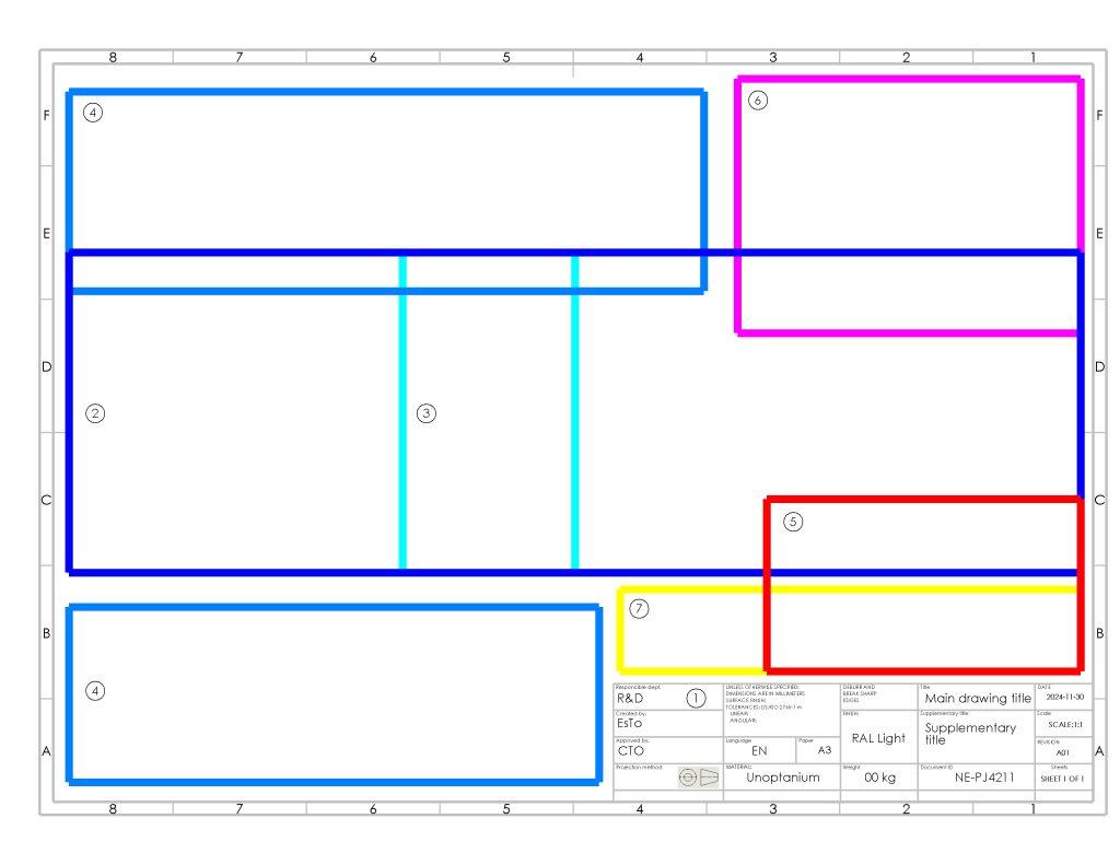
This approach works for all drawing sizes.
- Set up the title block
- The Orthographic views must be placed in the center of the drawing. This is where the part is portrayed in eg. 1. Angle view.
- The orthographic views can be supported by a section cut. This will for most cases be portrayed between the orthographic views to depict hidden details.
- Detailed views are enclosed areas that are enlarged for better understanding and to better allocate the required dimensions.
- Isometric view to illustrate the part in a tree dimensional space.
- Tables are often used to depict additional data such as hole location, Bill of materials and notes for manufacturing clarification.
- Generic notes to clarify specific details like what the ballons are indicating or how to interpret a specific detail.
Title block
All drawings need a identification block or table where all the drawing specific data is stored. Many CAD providers have templates for this but commonly for all is that they all need to include the following information.
Reference ISO 7200 Title block example.

What must it contain as a minimum.
- Responsible department, approved and created by
- Material and finish
- Tolerance reference
- Paper and scale
- Projection method
- Title and supplementary title
- Document ID, revision, language, date and sheets
Positioning of the title block
The title block must be placed in the bottom right corner of the drawing. This ensures that, when the drawing is folded according to ISO 5457 guidelines, the title block remains visible for easy identification.
Orthographic views
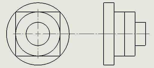
ISO 129
When selecting the first view (left) the part is often depicted from the top or from the side. The features on the part must be visual from the top/side. If all features cannot be present on the first view, choose the view that depicts most of the features and as natural as possible.
The right view shows how it looks when it is tilted onto the right side. Because this is a circular shape, the orientation does not change much. It changes depending on the shape. Keep this in mind when doing your selection of views.
It may be required to do multiple iterations depicting the part to get it right. Especially as complexity of the part increases.
Section views
Sometimes it is important to show hidden details that’s not visual from the outside. The hidden details are often depicted with a section cut-view.
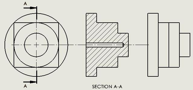
ISO 129
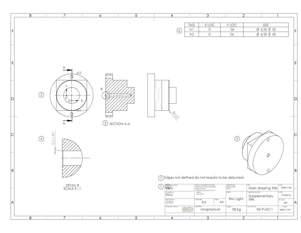
A hidden drilled hole in the bottom part is illustrated in a full section view. Depending on the part and need for details. This can be reduced to only include half or a partial section cut. Using only partial section cuts may allow for symmetrical dimensions while showing hidden details.
Detailed views
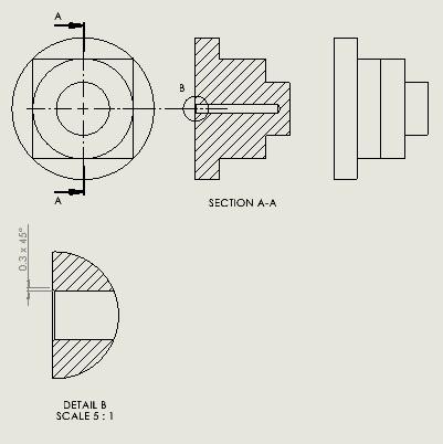
Details are great to use when the dimensions stack tight together in the original scale. Select a suitable scale to communicate the details and do so as simple as possible. Consider circular patterns to only document one instance and then describe the pattern for which it is required. Only depict what is required for functionality.
Isometric view
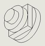
This display is used to give the reader a better understanding of how the part looks. It is often depicted in a different scale and sometimes in color. The location is often above the title block, but it can be located everywhere. Be sure to locate it where it makes sense and to select a perspective that supports the other views portrayed.
Tables
Table data can consist of many different types of information. Most are familiar with the Bill of Material, BOM. But there are many forms of tables, and they can consist of many different data types. When using a Table be sure to keep them as simple as possible and only convey what is required to fulfill the functionality.

This table details the coordinates for the center of the holes in X & Y direction. The origo is situated in the main view. View Example of simple drawing. The size determine the diameter and depth of the hole.
Notes
Notes are often used to communicate repetition or fabrication constraints or requirements. Keep it simple and short! If the information is fabrication related and requires clear description, then consider to make a drawing sheet where the information required can be portrayed in great detail and without any misunderstanding. Only notes are concise.

Example of simple drawing
You are now ready to start your own drawing and create great designs.


