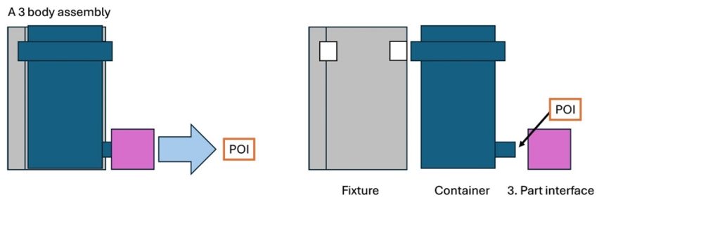
A tolerance chain, an essential aspect of design and manufacturing, can appear in multiple locations within a part or assembly. It’s crucial to focus on those chains directly impacting function and assembly. Properly placed dimensions on drawings are vital to clearly communicate requirements. Tolerance chain analysis helps determine the necessary manufacturing specifications for individual parts, whether during the initial function investigation or throughout the design process.

In an example assembly of three parts water container mounted onto a bracket that interfaces with a third part the point of interest (POI) is the interface between the third part and the container. To start a tolerance chain analysis, identify the items and their individual interfaces. Only after establishing this foundation can the analysis proceed.

Choose an origin (Origo), preferably a location relevant for fixing or positioning the part, such as a bolt or alignment side. The Origo is the starting point from which the tolerance chain is derived towards the POI. This system serves as a common conceptual starting point for all parts.

In this context, the Origo is marked with Datum features A & B. For this example, we examine the vertical positioning of parts, focusing on the fit at the interface of the third part. Each step of the interface is labeled with a notation: “I” for inward and “O” for outward, with upward notations being positive and downward ones negative. These are labeled as I1, I3, O2 (upward), and I2, O1 (downward).

In principle, the sum of these dimensions should be zero:
POI = 0, thus:
I1 + I3 + O2 = I2 + O1
0 = I1 + I3 + O2 – I2 – O1
Once this equation is established, requirements can be inserted, including specifications for POI space or tolerances on dimensions.
Deriving Equations for Worst-Case Scenarios
When considering worst-case scenarios, the goal is to identify the minimum space required for a successful fit.
For a concentric fit, the POI-Space can be determined by:
The condition is set as I3 < O2.
POI-Space.max = O2.max – I3.min
POI-Space.min = O2.min – I3.max
For eccentric alignment, the equations become:
Eccentric Alignment Ex.POI-Space.max = I1.min – I2.max + I3.min – O1.min + O2.max
Eccentric Alignment Ex.POI-Space.min = I1.max – I2.min + I3.max – O1.max + O2.min
To test these equations, it is helpful to start with simple numbers to check for errors. For instance, assume I1 can be manufactured with ±0.1mm accuracy, similarly for other components.
Ec.POI.Space.max= I3(-0,1)-I2(+0,1)+I3(-0,1)-O1(-0,1)+O2(+0,1) = -0,1
Ec.POI.Space.min = I1(+0,1)-I2(-0,1)+I3(+0,1)-O1(+0,1)+O2(-0,1) = +0,1
Conclusion
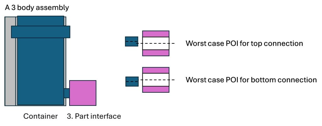
Since the spacing is negative downward, the increased space is equal to -0,1mm downward. This indicates that the change in dimension causes an eccentric displacement by 0,1 mm. At the top, there is an increase, and at the bottom, there is a decrease.
This eccentric displacement must be included in the O-ring function range of 0,5mm. Considering this, it results in a tolerance fit for the piston and hole of (0,5) – (0,1+0,1) = 0~0,3 mm tolerance for the O-ring space.
When designing a solution for a similar seal, the eccentric position must be included in the calculation of the design space for the O-ring. In this case, the O-ring space must include the space required for a fit of the piston into the hole of the third part interface, plus the space required to account for the eccentric position.

Summary
This article provides a guide on conducting a tolerance chain analysis, crucial in design and manufacturing. It begins with identifying components and their interfaces, then selecting an origin point (Origo). Notations assess inward and outward dimensions relative to the point of interest (POI), ensuring the sum of these dimensions equals zero.
The article also discusses deriving equations for worst-case scenarios, focusing on the minimum required space for a successful fit. Special attention is given to eccentric alignment and its effects on functional requirements, particularly for O-rings. The conclusion emphasizes that eccentric displacements and tolerances must be carefully considered to ensure fit and seal integrity. By following this structured approach, engineers can enhance the accuracy and reliability of their designs.
You are now equipped with the knowledge to conduct tolerance chain analyses in your designs. Approach the process with confidence and creativity, ensuring precision in your project outcomes. Best of luck!


